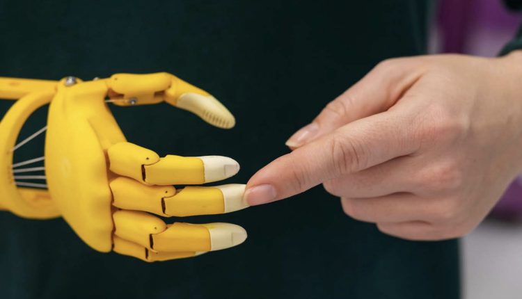
Mathematical analysis of underactuated fingers for prosthetic hands
Análisis matemático de dedos subactuados para manos protésicas
Enrique Soriano-Heras (1)*, Higinio Rubio (1) and Ramón Barber (2)
Nota para el lector: algunos símbolos y fórmulas incluidos en este artículo no han podido ser incorporados en lenguaje HTML. Por ello, para una mejor comprensión, se recomienda su lectura en el archivo adjunto «Documento PDF».
Note to the reader: some symboles and formulas included in this article have not been able to be incorporated into HTML language. Therefore, for a better understanding, it is recommended that you read the attached file «Document PDF».
Resumen
Las prótesis son un elemento de gran importancia y necesidad para muchas personas que han sufrido amputaciones o les falta algún miembro de su cuerpo; sin embargo, las prótesis suelen tener precios muy elevados, por lo que no son accesibles para todas las personas que desean utilizarlas. Por esta razón, los dedos subactuados en prótesis permiten una alternativa funcional y útil para ellos. En este artículo se realiza el diseño y análisis matemático de un dedo subactuado para prótesis de mano. Así, el dedo puede ser actuado por medio de un solo motor, siendo los dedos de las prótesis capaces de recuperar una posición preestablecida. El análisis matemático de los dedos subactuados para prótesis de mano permite comprobar el movimiento debido a los resultados de trayectoria, velocidad y aceleración. Utilizando la Matriz Jacobiana y el Método de Newton-Raphson se proporciona un modelo lineal que ayuda al posterior control de velocidades y aceleraciones de cada eslabón del dedo. Para el modelo se han considerado dimensiones de una mano de hombre y de mujer. Los resultados son apropiados para prótesis de mano, con velocidad suficiente, pero no demasiado alta, lo que ayuda a prolongar la vida útil del mecanismo.
Palabras clave
Dedos subactuados, prótesis de mano, análisis matemático
Abstract
Prostheses are an element of great importance and necessity for many people who have suffered amputations or lack a member of their body; however, prostheses tend to have very high prices, so they are not accessible to all people who want to use them. For this reason, underactuated fingers in prostheses allow a functional and useful alternative for them. In this article, the design and mathematical analysis of an underactuated finger for hand prostheses is carried out. Thus, the finger can be actuated by means of a single motor, being the protheses fingers capable of recovering a pre-established position. The mathematical analysis of the underactuated fingers for prosthesis hands allows checking the movement due to the results of trajectory, velocity, and acceleration. Using the Jacobian Matrix and Newton-Raphson Method proportionate a linear model that helps the subsequent control of velocities and accelerations of each link of the finger. For the model, dimensions of a man and woman hand have been considered. Results are appropriate for hand prostheses, with sufficient velocity but not too high, which helps to prolong the useful life of the mechanism.
Keywords
Underactuated fingers, hand prothesis, mathematical analysis
Recibido/received: 15/09/2024 Aceptado/accepted: 20/10/2024 1.
1. Departamento de Ingeniería Mecánica, Universidad Carlos III de Madrid, Avda. de la Universidad, 30, 28911 Leganés-Madrid, Spain; hrubio@ing.uc3m.es (H.R.)
2. Departamento de Ingeniería de Sistemas y Automática, Universidad Carlos III de Madrid, Avda. de la Universidad, 30, 28911 Leganés-Madrid, Spain; rbaber@ing.uc3m.es (R.B.) *Correspondence: esoriano@ing.uc3m.es
1. Introduction
In the United States, there are approximately 2.1 million people who suffer from an amputation, representing about 0.63% of population. It is projected that the number of people living with the loss of a limb will more than double by the year 2050 to 3.6 million, may be a result of surgery, trauma, disease, or due to a congenital manifestation (Ziegler-Graham, MacKenzie, Ephraim, Travison, & Brookmeyer, 2008). Upper extremity amputation affects approximately 41,000 persons or 3% of the limb absence population, majority of amputees seek some type of prosthesis to replace their upper limbs (Latour, 2022). However, access to prostheses with an adequate functionality is not usually easy, although this market has been enormously boosted in recent years thanks to 3D printing, which is a powerful tool in this field, hand prostheses manufactured by 3D printing usually have a price that ranges between USD 300 and USD 5,000. Prostheses with more advanced technology, depending on many factors, such as materials, functionality or design, can be raised at prices between USD 20,000 and USD 60,000 (Gretsch et al., 2016; ten Kate, Smit, & Breedveld, 2017). Cosmetic prostheses, with very simple mechanisms and limited functionality, but with high degree of realism, also reach high prices, in the case of the company Dianceht, the full hand cosmetic prosthesis is priced at 6,000 USD, and hand and forearm, USD 9,750 (Dianceht, 2022).
Human hands play a vital role in the daily life of any person, being one of the fun-damental means of interaction with the outside world. Their complex anatomy, as result of years of evolution, is one of the most important differentiating elements of humans with multitude of movements, sensitive capacities, and possible functionalities, within the developed use that people make of them, it makes their technological reproduction very complicated (Bicchi, 2000; Cobos, Ferre, Sanchez Uran, Ortego, & Pena, 2008; Controzzi, Cipriani, & Carrozza, 2014; Li, Wang, & Liu, 2022), and for this reason expensive as shown above. The functions of prothesis hands are divided into two main categories: motor and sensory. Motor includes grasping, holding, pushing, pulling, hitting, and manipulating; sensory considers the exploration of surfaces, the sensation of pressure, force and, vibration (Piazza, Grioli, Catalano, & Bicchi, 2019). This paper represents a contribution to the motor capacity of the hands, seeking to achieve gripping movements in a robust and simple way, providing the model with a single actuator per finger.
Prothesis hands are actuated by two approaches, fully actuated (Borst C, Fischer M, Haidacher S, 2003; Butterfass, J., Fischer, M., Grebenstein, M., Haidacher, S., & Hirzinger, 2004; Butterfass, Grebenstein, Liu, & Hirzinger, 2001; Kawasaki, Komatsu, & Uchiyama, 2002) and underactuated mechanisms (Birglen, Laliberté, & Gosselin, 2007; Mottard, Laliberté, & Gosselin, 2017; Sabetian, Feizollahi, Cheraghpour, & Moosavian, 2011; Sarac, Solazzi, Sotgiu, Bergamasco, & Frisoli, 2017; Soriano-Heras, Blaya-Haro, Molino, & De Agustín del Burgo, 2018). Fully actuated devices are heavy, expensive, difficult to as-semble, and with sophisticated sensing elements, and complicated control laws making complex experimental implementation. Otherwise, underactuated systems have more degrees of freedom (DOF) than degrees of actuation, allowing passive motion between DOF, which are determined by the equilibrium of the contact forces with passive elements such as springs, clutches, or brakes. In consequence, underactuated robotic hands use fewer motors, saving space, weight, and cost. Nevertheless, some disadvantages arise from the underactuated nature, i.e. the individual control of each joint is not possible, reducing dexterous capabilities (Kontoudis, Liarokapis, Vamvoudakis, & Furukawa, 2019; Ozawa & Tahara, 2017; Piazza et al., 2019). Another issue in underactuated robotic hands is adaptivity, when a new actuator generation and technology have been implemented (Aukes et al., 2014; Deimel & Brock, 2016; Odhner et al., 2014; Soriano-Heras et al., 2018).
Some previous models of the finger have been proposed previously (S. Reza Kashef, Amini, & Akbarzadeh, 2020) the cinematic configuration of two phalanges un-der-actuated finger is shown, but the mathematic is not provided. Birglen et al. (2007) configurations of a two and three phalange underactuated finger provided for a link-age-driven finger and a tendon-driven finger, but model and mathematical equations are focused on obtaining an analytical expression of the normal contact forces, not providing information about velocities and accelerations of the model. Massa, Roccella, Carrozza, & Dario, n.d. consider a tendon solution using a three-phalange model and Lagrange for-mulation with the purpose of studying the flexibility of the chain, not providing infor-mation about velocities and accelerations of the model. S. R. Kashef, Davari, & Akbarzadeh (2018) used same two-phalange finger model showing the cinematic con-figuration of the finger and the cinematic and dynamic equations of the finger using La-grange method, but it only compares the angular displacements of the links with the output of the software model of the finger.
In this paper we developed a matrix model using Jacobian matrix that proportionate an easy way to model the finger having easy access to position speed and acceleration that can help a subsequent control in state space. In this paper the complete design and mathematical analysis of underactuated mechanisms-based fingers for prosthetic hands are proposed. The designed finger, when flexed, describes an arc trajectory at its end, which is achieved due to an underactuated mechanism actuated from its lower area. It connects with the palm, and it is moved by the prosthetic hand actuator.
The model provides full information about position, velocity and acceleration of each link. Using the Jacobian Matrix and Newton-Raphson Method proportionate a linear model that helps the subsequent control of positions and velocities of each link of the finger. For the model, dimensions of a man and woman hand have been considered.
2. Prosthetic fingers design
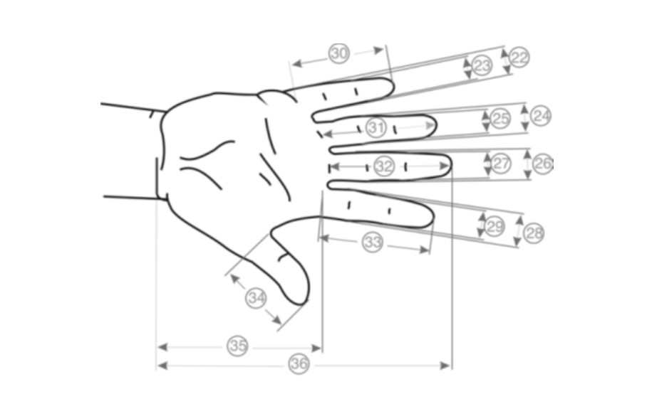
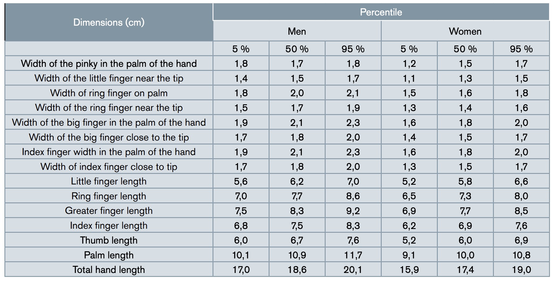
Standardized dimensions according to DIN 33 402-2 of the human hand are showed in Figure 1 and Table 1 (DIN, 2019). To design a prosthesis or any element of equipment or tooling, it is necessary to know the standards in which the dimensions of the hands in men and women are located.
As a sample for our study, finger dimensions have been made considering the parameters set in the cited standard, measuring from the base to the tip of the finger 80 mm, which is the mean value between the average dimension (percentile 50%) of the longest finger in men and women. On the other hand, the front and lateral width of the finger is also the mean value between the average measurement of men and women of the width of the longest finger in the palm of the hand. However, the algorithm developed in this paper allows any measurement.
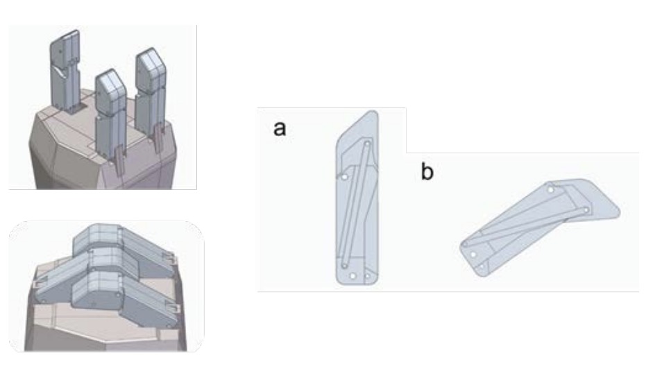
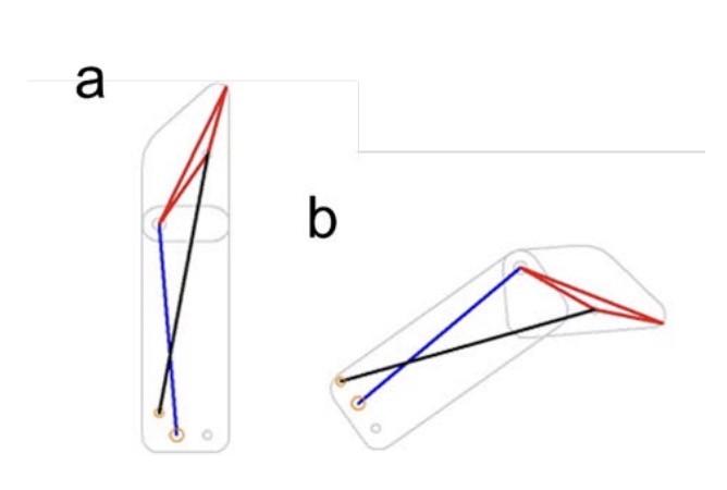
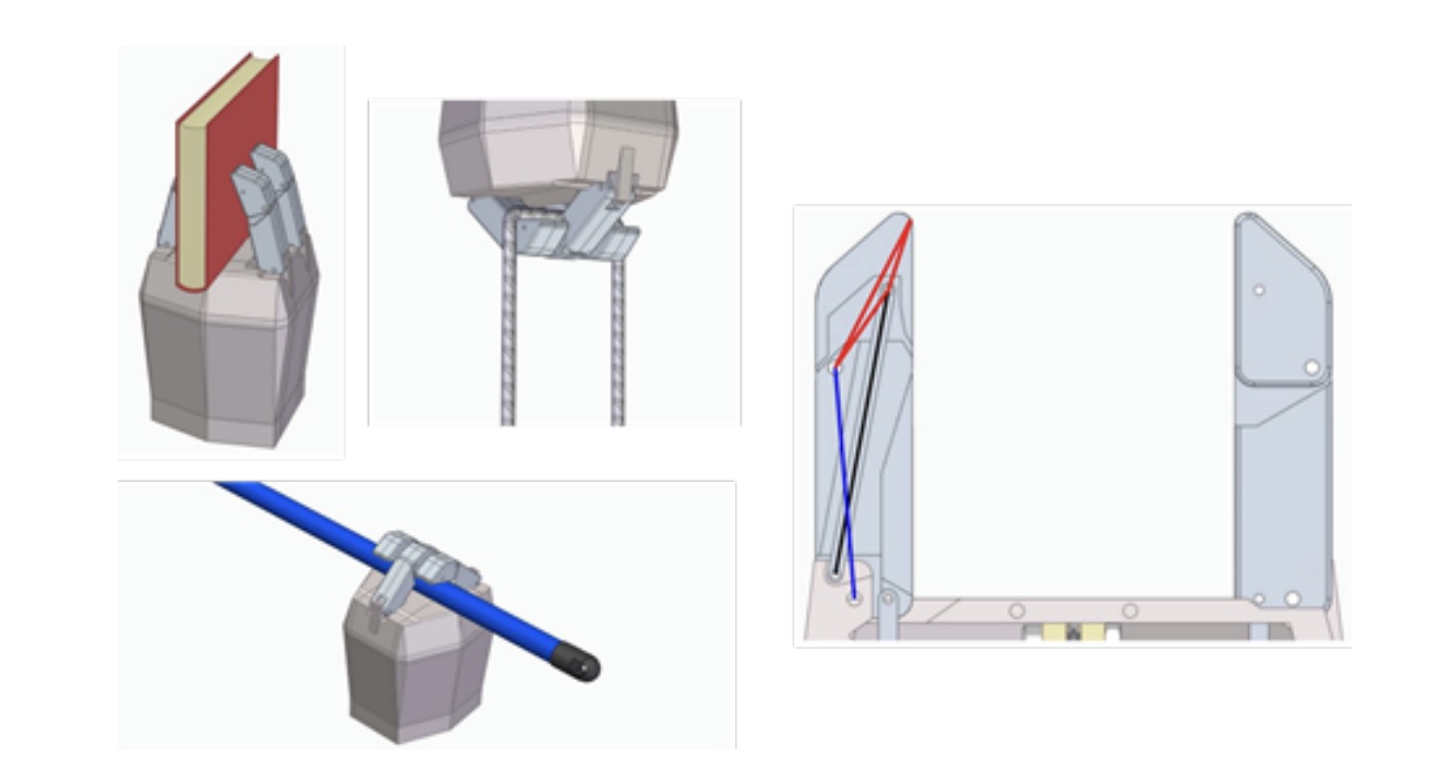
Fingers, when flexed, describe an arc trajectory at their edge, which is achieved due to an underactuated mechanism, started from its lower zone, which connects it with a mobile part activated by the prosthetic hand actuator. Figures 2, 3, and 4 show the 3D model of the stretched and flexed finger, the diagram of its links, also stretched and flexed, and the combination of the 3D and the diagram, respectively.
Once the mechanism and its 3D model have been designed, the DOFs of the mechanism can be determined using the Grübler criterion, equation 1. Where G are DOFs of the mechanism, N is the number of links, p1 is the number of kinematic pairs of 1 DOF, p2 is the number of kinematic pairs with 2 DOFs.
![]() As shown in Figures 3 and 4, the underactuated mechanism has three elements plus the ground, and has four kinematic pairs of 1 degree of freedom. Therefore, applying equation 1, a result of 1 DOF is obtained. This DOF corresponds to the flexion and extension movement of each of the fingers of the prosthetic hand.
As shown in Figures 3 and 4, the underactuated mechanism has three elements plus the ground, and has four kinematic pairs of 1 degree of freedom. Therefore, applying equation 1, a result of 1 DOF is obtained. This DOF corresponds to the flexion and extension movement of each of the fingers of the prosthetic hand.
3. Mechanism kinematics
In the development of the mechanism of the articulated fingers for prosthetic hands, it is important to study its kinematics to examine the trajectory that the finger describes and its velocity and acceleration, thus analysing and verifying the mechanism.
To carry out the kinematic study, natural coordinates have been used, in which the reference points of each link are in the kinematic pairs. With natural coordinates, each element is located independently of the rest, which gives immediate geometric interpre-tation from the coordinates.

3.1. Coordinate vector and initial conditions
First, it is necessary to define the vector of natural coordinates of the mechanism, in addition to the constant parameters. The coordinates are variables changing their value as the mechanism moves.
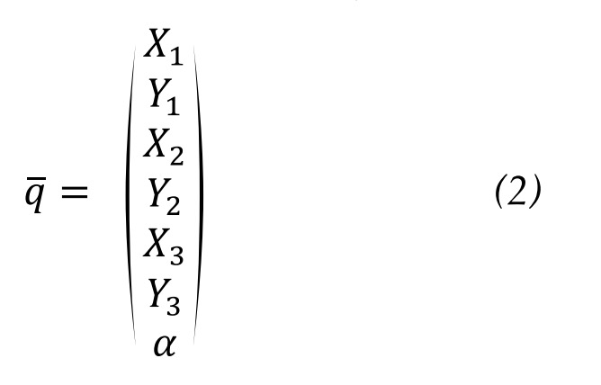
Figure 5 shows the mechanism links. Constant parameters and coordinates are pre-sented below. Points 1, 2, and 3 and the angle of rotation of link 1, which initiates the movement, are defined as natural coordinates. Hence, parameters are XA, YA, XD, YD, L1, L2, L12, L13, L23 and coordinates are X1, Y1, X2, Y2, X3, Y3, ?. Therefore, the coordinate vector is defined by equation 2.
 3.2. Constraints vector
The constraint equations are relationships between the different coordinates that have been established, thus defining the mechanism. Equation 3 is used to determine the number of constraint equations needed. Where r is the number of constraint equations, n is the number of coordinates and G is the number of DOFs of the mechanism.
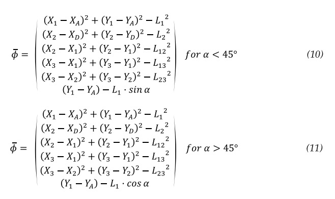
![]() The number of constraint equations obtained is 6, equations 4 to 9. They are defined by the rigid links 1, 2, 12, 13 and 23 and the equations 8 and 9 are defined by the rotation angle of link 1, ?.
The number of constraint equations obtained is 6, equations 4 to 9. They are defined by the rigid links 1, 2, 12, 13 and 23 and the equations 8 and 9 are defined by the rotation angle of link 1, ?.

Therefore, the constraint vector is in equations 10 an 11.
 3.3 System Linearization, Jacobian Matrix and Newton Raphson Method
The solution for the constraint equations is obtained by means of an iterative loop. To build the iterative loop it is first necessary to linearize the system of constraint equations (symbol). So, it is expanded in Taylor series from its initial position (symbol), equation 12, where (symbol) is the Jacobian Matrix from constraint equations.
 According to equation 3 the linear system has six equations, where (symbol) is the Jacobian matrix of the constraint equations 4 to 9. In the case the Jacobian matrix is in equation 13 and 14. Once the Jacobian matrix has been determined, the values of the approximate initial position (symbol) , are
 substituted into equation 12, and the vector of coordinates (symbol) is solved, it is the result of the first iteration, called . Next, this vector is replaced (symbol) into the place where (symbol) was initially, clearing up (symbol) again, which is now called (symbol). The process is repeated until the error is small enough and the constraint equations are satisfied, by applying the Newton-Raphson method, equation 15.
 It is important to note that when applying the Jacobian matrix in equation 15, the DOF, defined by the angle (symbol), is a known value, since it depends on the value given to it for the initial position, time, and known angular velocity (symbol), therefore, its derivative is zero. So, it is possible to cancel its column in the Jacobian matrix and its row in vector (symbol), the Jacobian matrix results with six rows and six columns and the vector (symbol) with six rows and one column. Therefore, an iterative loop is solved until the solutions for the coordinate vector are found that solve the constraint equations.
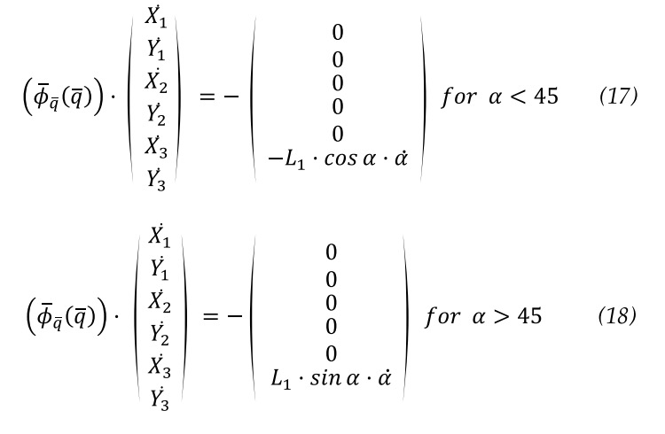
 3.4. Velocity determination
The differentiate with respect to time of determines the variation of the velocity value for the coordinates, knowing the initial velocity of the underactuated mechanism, equation 16.
Therefore, velocity for the finger underactuated mechanism is in equations 17 and 18.
![]() Where (symbol) is the derivative of (symbol), (symbol), considering 0 for the acceleration a. It is a simple system of equations, which can be solved directly, obtaining the values of the velocities for the coordinates.
Where (symbol) is the derivative of (symbol), (symbol), considering 0 for the acceleration a. It is a simple system of equations, which can be solved directly, obtaining the values of the velocities for the coordinates.
 3.5. Acceleration determination
The acceleration problem starts from the known acceleration of the underactuated mechanisms in a specific position and velocity. Once again, the system of velocity equations (symbol) is derived with respect to time, equation 19.

With known position and velocity and expanding the system until the DOF multiplied by the acceleration vector is obtained equations 20 and 21.

 In this case, the value of (symbol), is directly the acceleration (symbol) , which is considered zero. This system of equations can also be solved directly.


4. Results
To perform all the calculations of the position, velocity and acceleration problem, Matlab software has been used, which facilitates the calculation of matrices and allows the loops to be carried out adequately and accurately. Figure 6 shows the flowchart for the calculation of the position problem.
For the experiments, average parameters between the man’s and woman’s hands in cm have been considered: L1 = 50, L2 = 60, L12 = 10, L13 = 20, L23 = 10. A and D points are separate I X = 5 and Y = 5. Rotation movement is applied in A, see Figure 5.

The trajectory described by the finger in its movement and the position values with respect to the origin of coordinates for all its points, in the initial position, for 0.6 seconds, 1.2 s, 1.8 s and the total time of 2.4 s in the final position are shown in Figures 7 to 9 and in Table 3.
The trajectory described by the finger in its action is verified and validated, making a movement like the flexion of a human finger, focused on a prosthesis that performs a gripper movement. In addition, the position of its coordinates, obtained at the beginning, at the end at 25 %, 50 % and 75 % of the total action time. The position of the end of the finger being especially useful, point 3, see Figure 5, and the angle of evolution of the lower phalanx.
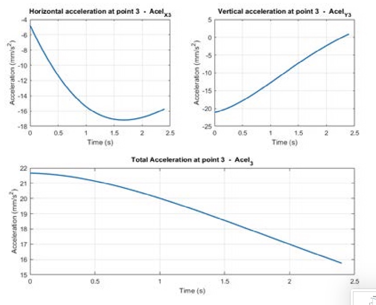
The values and graphs of the evolution of the velocity and acceleration of the lower phalanx in the process of finger actuation are in Figures 8 to 9 and in Tables 3 to 4.

The experiments validate the cinematic model according to the design tool, providing the velocity and acceleration of the final points of the links, that was one of the objectives of the model to be able achieve a more precise control of the finger.
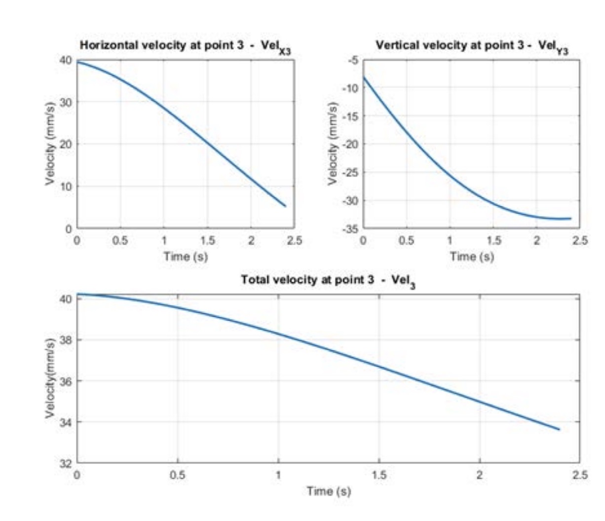
The movement of the phalanx of the finger is propitiated by the simultaneous action in other finger points, 1 and 2, see Figure 5, which causes a negative variable acceleration in the lower phalanx. As the movement progresses, a decrease in the lower phalanx ve-locity is caused. This decrease in velocity of 16.4 %, from 40.23 mm/s to 33.63 mm/s, is favourable for the daily performance of the prosthetic hand, since it will always begin its movement with a higher velocity than the velocity with which contact with any object will occur.
On the other hand, the velocity and acceleration results are very consistent with the movement described, being carried out at a sufficient but not too high velocity, which contributes to prolonging the useful life of the mechanism.

5. Conclusions
The fingers arise in the hand from a base located in its lower part, which can be used to support objects and facilitate performance reducing the load exerted on the fingers. All this has been designed in this way to prolong the useful life of the prosthesis and to minimize maintenance, reducing costs.
A kinematic analysis of the movement described by the fingers has been carried out, calculating, and representing trajectory, velocity, and acceleration. Thus, the movement of the finger is checked, which describes a trajectory like that of a real finger, sweeping the lower phalanx of the finger, which triggers the movement, an angle of 55 degrees. The velocity of the tip of the finger is reduced as the movement progresses due to a variable negative acceleration in the upper phalanx, from 40.23 mm/s to 33.63 mm/s, which re-duces the velocity at the moment of contact with the object to be grasped. These are ap-propriate results for a hand prosthesis, with sufficient velocity but not too high, which helps prolong the useful life of the mechanism.
The model provides full information about position, velocity and acceleration of each link. Using the Jacobian Matrix and Newton-Raphson Method proportionate a linear model that helps the subsequent control of positions and velocities of each link of the finger. As future work, it will be considered to design a state space controller that control torques considering the velocity and acceleration of the phalanges that allows grip to grasp delicate objects with precision.
Author contributions: Conceptualization, E.S., H.R. and R.B.; methodology, H.R and R.B.; soft-ware, H. R. and E.S.; validation, H.R and R.B.; formal analysis, E.S and H.R.; investigation, E.S., H.R. and R.B.; resources, H.R. and E.S.; data curation, R.B.; writing—original draft preparation, E.S.; writing—review and editing, H.R. and R.B.; visualization, H.R.; supervision, E.S.; project ad-ministration, E.S.; funding acquisition, H.R. and R.B. All authors have read and agreed to the published version of the manuscript.
Funding: This publication is part of the R&D&I project PLEC2021-007819 funded by MCIN/ AEI/10.13039/501100011033 and by the European Union NextGenerationEU/PRTR.
Data availability statement: Not applicable. Acknowledgments: The authors wish to acknowledge the financial support of the Spanish gov-ernment’s State Investigation Agency Grant Number PID2020-116984RB-C22.
Conflicts of interest: The authors declare no conflict of interest. The funders had no role in the design of the study; in the collection, analyses, or interpretation of data; in the writing of the manuscript, nor in the decision to publish the results.
References
Aukes, D. M., Heyneman, B., Ulmen, J., Stuart, H., Cutkosky, M. R., Kim, S., … Edsinger, A. (2014). Design and testing of a selectively compliant underactuated hand. The International Journal of Robotics Research, 33(5), 721–735. https://doi. org/10.1177/0278364913518997
Bicchi, A. (2000). Hands for dexterous manipulation and robust grasping: a difficult road toward simplicity. IEEE Transactions on Robotics and Automation, 16(6), 652–662. https:// doi.org/10.1109/70.897777
Birglen, L., Laliberté, T., & Gosselin, C. (2007). Underactuation between the Fingers. https://doi.org/10.1007/978- 3-540-77459-4_6 Borst C, Fischer M, Haidacher S, L.
H. (2003). DLR Hand II: Experiments and Experiences with an Anthropomorphic Hand. Proceedings – IEEE International Conference on Robotics and Automation. Taipei, Taiwan: IEEE.
Butterfass, J., Fischer, M., Grebenstein, M., Haidacher, S., & Hirzinger, G. (2004). Design and experiences with DLR hand II. Proceedings World Automation Congress, 105–110. Retrieved from https://ieeexplore.ieee.org/ abstract/document/1438537?casa_token=7kk6ESEgeLQAAAAA:gn3HmEX0UDvfD1kNd-wxNBlDGyl8LQgFZ_uU1ASJT1IkmUvOByUSlzgI7l-5jpZvP7-LAeTQ
Butterfass, J., Grebenstein, M., Liu, H., & Hirzinger, G. (2001). DLRHand II: next generation of a dextrous robot hand. Proceedings 2001 ICRA. IEEE International Conference on Robotics and Automation (Cat. No.01CH37164), 1, 109–114. https://doi.org/10.1109/ ROBOT.2001.932538
Cobos, S., Ferre, M., Sanchez Uran, M. A., Ortego, J., & Pena, C. (2008). Efficient human hand kinematics for manipulation tasks. 2008 IEEE/ RSJ International Conference on Intelligent Robots and Systems, 2246–2251. https://doi.org/10.1109/ IROS.2008.4651053
Controzzi, M., Cipriani, C., & Carrozza, M. C. (2014). Design of Artificial Hands: A Review. https://doi. org/10.1007/978-3-319-03017-3_11
Deimel, R., & Brock, O. (2016). A novel type of compliant and underactuated robotic hand for dexterous grasping. The International Journal of Robotics Research, 35(1–3), 161–185. https:// doi.org/10.1177/0278364915592961
Dianceht. (2022). Pricing list. Retrieved from https://www.manosydedos. com/precios.html#
DIN. Ergonomics – Human body dimensions – Part 2: Values. , (2019).
Gretsch, K. F., Lather, H. D., Peddada, K. V, Deeken, C. R., Wall, L. B., & Goldfarb, C. A. (2016). Development of novel 3D-printed robotic prosthetic for transradial amputees. Prosthetics & Orthotics International, 40(3), 400–403. https://doi. org/10.1177/0309364615579317
Kashef, S. R., Davari, M., & Akbarzadeh, A. (2018). A robust design of a prosthetic finger and its dynamic analysis. 2018 6th RSI International Conference on Robotics and Mechatronics (IcRoM), 135–140. https://doi. org/10.1109/ICRoM.2018.8657605
Kashef, S. Reza, Amini, S., & Akbarzadeh, A. (2020). Robotic hand: A review on linkage-driven finger mechanisms of prosthetic hands and evaluation of the performance criteria. Mechanism and Machine Theory, 145, 103677. https://doi.org/10.1016/j. mechmachtheory.2019.103677
Kawasaki, H., Komatsu, T., & Uchiyama, K. (2002). Dexterous anthropomorphic robot hand with distributed tactile sensor: Gifu hand II. IEEE/ ASME Transactions on Mechatronics, 7(3), 296–303. https://doi. org/10.1109/TMECH.2002.802720
Kontoudis, G. P., Liarokapis, M., Vamvoudakis, K. G., & Furukawa, T. (2019). An Adaptive Actuation Mechanism for Anthropomorphic Robot Hands. Frontiers in Robotics and AI, 6. https://doi.org/10.3389/ frobt.2019.00047
Latour, D. (2022). Advances in Upper Extremity Prosthetic Technology: Rehabilitation and the Interprofessional Team. Current Physical Medicine and Rehabilitation Reports, 10(2), 71–76. https://doi.org/10.1007/ s40141-022-00342-x
Li, R., Wang, H., & Liu, Z. (2022). Survey on Mapping Human Hand Motion to Robotic Hands for Teleoperation. IEEE Transactions on Circuits and Systems for Video Technology, 32(5), 2647–2665. https://doi. org/10.1109/TCSVT.2021.3057992
Massa, B., Roccella, S., Carrozza, M. C., & Dario, P. (n.d.). Design and development of an underactuated prosthetic hand. Proceedings 2002 IEEE International Conference on Robotics and Automation (Cat. No.02CH37292), 4, 3374– 3379. https://doi.org/10.1109/ROBOT.2002.1014232
Mottard, A., Laliberté, T., & Gosselin, C. (2017). Underactuated tendon-driven robotic/prosthetic hands: design issues. Robotics: Science and Systems XIII. https://doi.org/10.15607/ RSS.2017.XIII.019
Odhner, L. U., Jentoft, L. P., Claffee, M. R., Corson, N., Tenzer, Y., Ma, R. R., … Dollar, A. M. (2014). A compliant, underactuated hand for robust manipulation. The International Journal of Robotics Research, 33(5), 736–752. https://doi. org/10.1177/0278364913514466
Ozawa, R., & Tahara, K. (2017). Grasp and dexterous manipulation of multi-fingered robotic hands: a review from a control view point. Advanced Robotics, 31(19–20), 1030–1050. https://doi.org/10.1080/01691864.2017. 1365011
Piazza, C., Grioli, G., Catalano, M. G., & Bicchi, A. (2019). A Century of Robotic Hands. Annual Review of Control, Robotics, and Autonomous Systems, 2(1), 1–32. https:// doi.org/10.1146/annurev-control-060117-105003
Sabetian, P., Feizollahi, A., Cheraghpour, F., & Moosavian, S. A. A. (2011). A compound robotic hand with two under-actuated fingers and a continuous finger. 2011 IEEE International Symposium on Safety, Security, and Rescue Robotics, 238–244. https://doi.org/10.1109/ SSRR.2011.6106774
Sarac, M., Solazzi, M., Sotgiu, E., Bergamasco, M., & Frisoli, A. (2017). Design and kinematic optimization of a novel underactuated robotic hand exoskeleton. Meccanica, 52(3), 749– 761. https://doi.org/10.1007/s11012- 016-0530-z
Soriano-Heras, E., Blaya-Haro, F., Molino, C., & de Agustín del Burgo, J. M. (2018). Rapid prototyping prosthetic hand acting by a low-cost shape-memory-alloy actuator. Journal of Artificial Organs, 21(2), 238–246. https:// doi.org/10.1007/s10047-017-1014-1
Ten Kate, J., Smit, G., & Breedveld, P. (2017). 3D-printed upper limb prostheses: a review. Disability and Rehabilitation: Assistive Technology, 12(3), 300–314. https://doi.org/10.10 80/17483107.2016.1253117
Ziegler-Graham, K., MacKenzie, E. J., Ephraim, P. L., Travison, T. G., & Brookmeyer, R. (2008). Estimating the Prevalence of Limb Loss in the United States: 2005 to 2050. Archives of Physical Medicine and Rehabilitation, 89(3), 422–429. https://doi. org/10.1016/j.apmr.2007.11.005


